
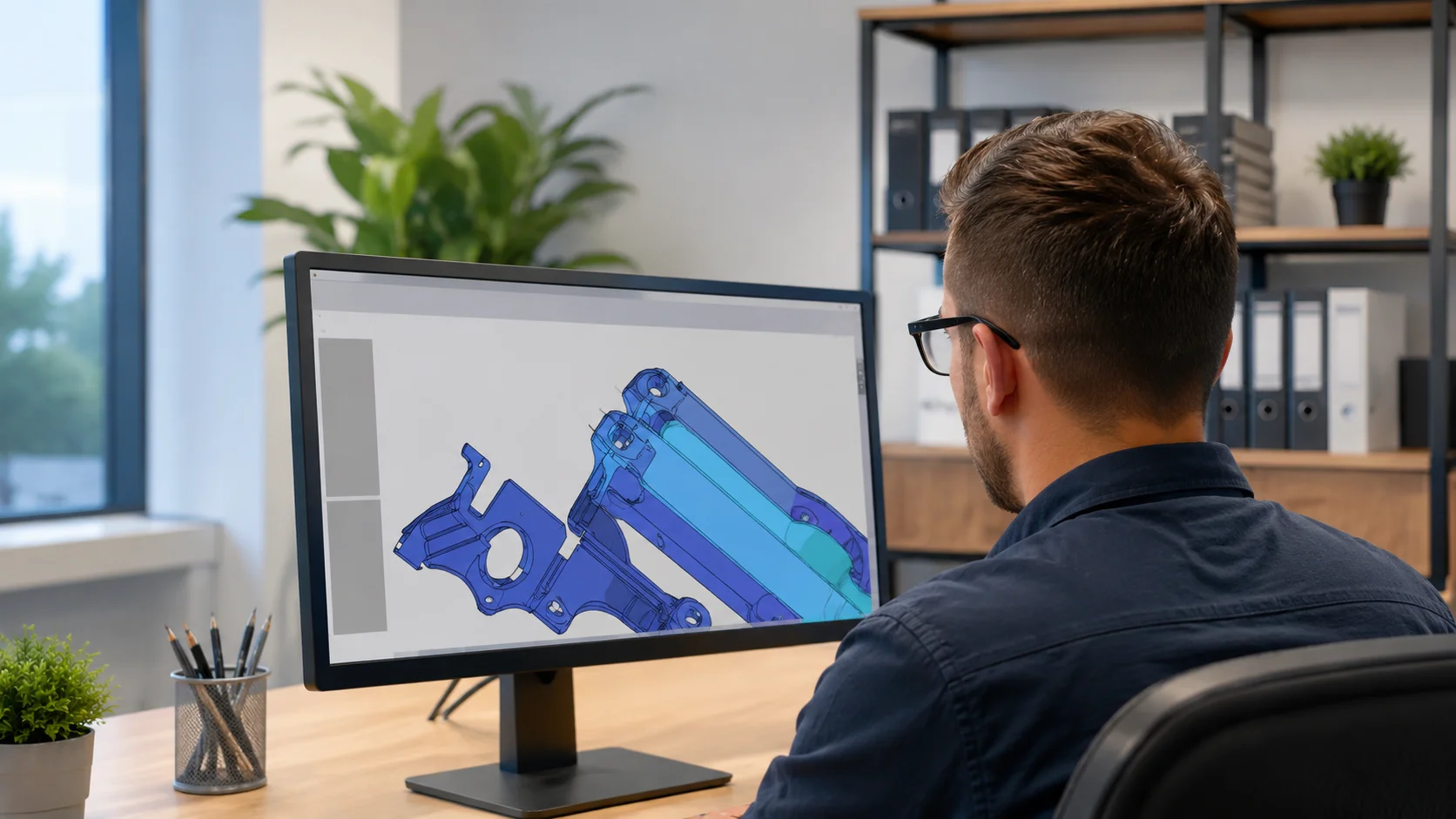
A design for manufacturing review is not a quotation and not a redesign. It is a structured read of a 3D model against two questions: can this tool be built the way it is drawn, and will this part come out of it consistently for the life of the program.
Every issue found at this stage costs an email. The same issue found after T1 samples costs steel, and after mass production has started it can cost a tool.
Geometry
- Wall thickness map. Nominal wall, uniformity, and every local thick section that will sink or warp.
- Draft. Every face parallel to the pull direction, on the core side as well as the cavity side, checked against the specified surface finish.
- Ribs and bosses. Base thickness relative to nominal wall, height, spacing, and whether bosses are connected by gussets or blended into a mass.
- Radii. Sharp internal corners are stress concentrators and flow restrictions; they get called out for a fillet.
- Undercuts. Any feature that will not release in the pull direction, and whether it can be redesigned out or needs a side action or lifter.
Tooling consequences
The second pass reads the same model as a tool builder.
- Parting line. Where the tool splits, and whether that line falls on a surface the customer considers cosmetic.
- Gate location and type. Where material enters, what vestige it leaves, and whether the resulting flow path fills the part evenly.
- Weld lines. Where two flow fronts will meet, since that is both a cosmetic mark and the weakest line in the part. If a weld line lands across a snap hook or a load path, something needs to move.
- Ejection. Where ejector pins can push without deforming the part or leaving witness marks on a visible face.
- Venting and cooling. Whether trapped air will burn the part, and whether thick sections can actually be cooled.
Specification gaps
The third pass is about what the drawing does not say. Which dimensions are genuinely critical and which are reference. Which surfaces are cosmetic and to what standard. What the colour target is and how it will be verified. Whether the part will be printed, welded, or assembled afterwards, since each of those constrains geometry.
These gaps cause more disputes than geometry does, because both sides assume an unstated requirement was understood.
What to send
A STEP or IGES model is the working minimum. A 2D drawing with critical dimensions and tolerances, an indication of cosmetic surfaces, the target resin and colour, and the expected annual volume turns the review from a moldability opinion into something close to a manufacturing plan. Annual volume in particular drives cavitation and therefore the tool quote, so a review without it can only be provisional.
Send a drawing and we will return feedback within one business day.